Extreme Speedo Rescue
Posted: Tue Dec 03, 2019 6:38 pm
This is something between a blog post, a how-to, and a question thread, so the electrical forum felt like the right place for it.
My grey ES was supposed to be restoration project to give me something to fix when I'm not already fixing the green GT, but the other half has been using it to commute in so not a huge amount has happened to it, until she told me last week that the speedo had stopped working. "No problem", I thought naievely, "I'll repair a few connections here and there, give it a clean, and it'll be back up and running in no time. How wrong I was.
Being an '88 car it has the older style pins-through-the-board arrangement to connect to the speedo rather than the nicer ribbon cable and blue connector found on the back of newer clusters, and when I got it out it looked like this:
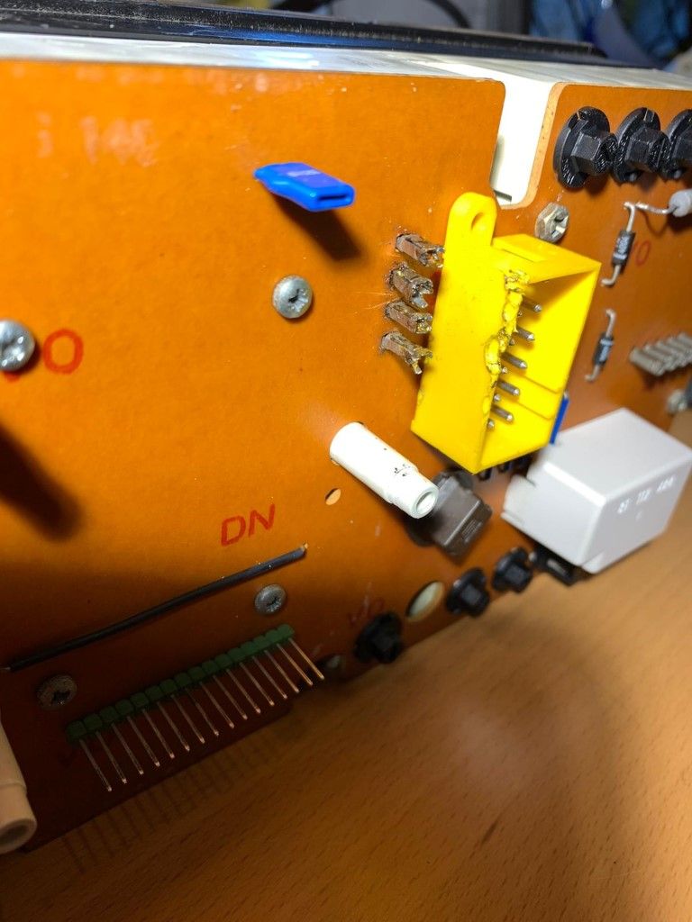
To my eyes this looks like it was repaired by an agry gorilla. In general I support the return of public flogging for people who solder those pins in an attempt to do a quick fix on the speedo, but this was something else. Not only were the pins soldered solid, they were all bent out of shape and he's managed to melt the plastic connector and warp it, which might go some way to explaining how hard it was to unplug. They're never easy, but this one was noticeably less willing to come out than normal.
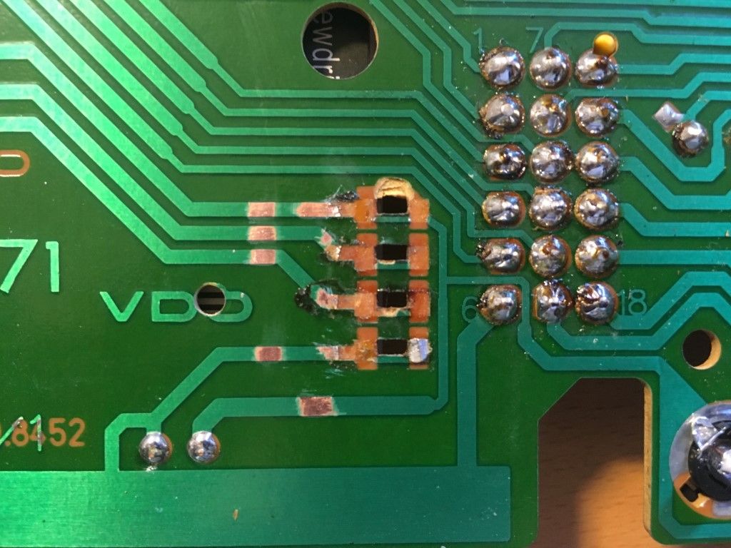
I had to apply far more heat and brute force than I would have liked to get the thing apart. Owing to the design (and the damage) it was very hard to remove the solder by conventional means, and when I finally got the board off, the underside looked like this:
Not pleasant. A combination of heat and shearing force ripped the pads straight off the board. I'll take some responsibility for that, but I'll also lay some blame at the door of the aforementioned primate who forced me to take this drastic action in the first place.
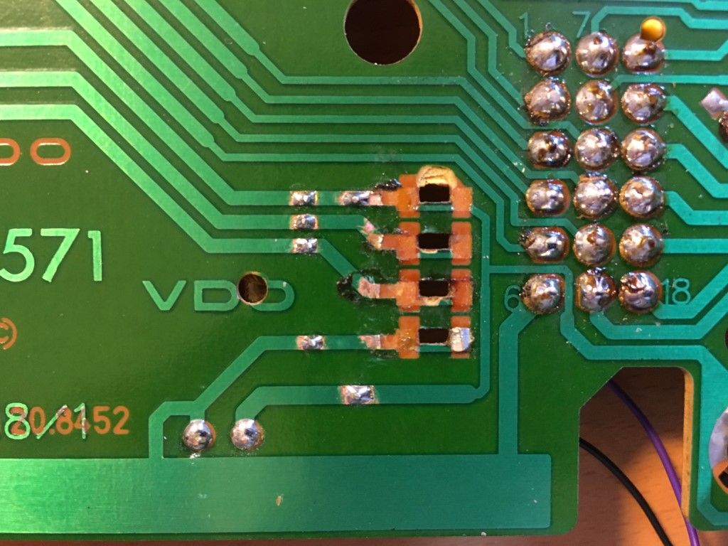
I did the usual re-flow job on the big connectors and then paused to consider my next move toward getting the speedo connected again. Was I disheartened? Slightly, but not enough to give up. I exposed some nice clean copper further up the traces and ended up with this:
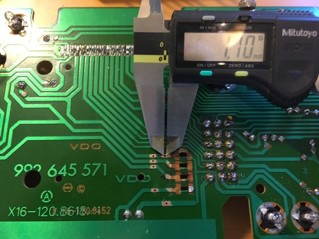
Note that the top speedo pin actually has a trace running straight through to the other side, so I exposed some extra copper on that along with some on the trace below the pins. Next, I drilled out some holes, starting at 0.6mm and ending at 1.1mm, going very slowly. These are old boards and I didn't want to risk ripping the whole trace off the surface (again):
Thankfully, these are very simple single-layer boards so can be drilled through without risk of destroying something in the middle. In fact, all I'm really doing here is adding to the existing through-hole connections on the other side. A bit of flux and solder later and it almost looks like they were supposed to be there:
Looking at the the other side of the board it becomes easier to see what's going on:
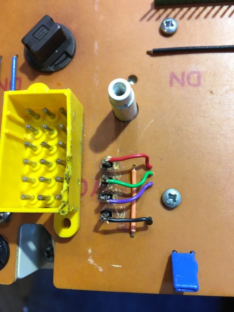
The orange single-core is bridging across that link from the top speedo pin to the trace at the bottom that was broken (and doesn't even look out of place compared to the similar black wire in the top right that's there from the factory), and the red, green, purple and black connectors are playing the role of the now-destroyed headers. The observant reader will notice that I soldered them again, but this time around I know that the underside of the board is in good condition because I've seen it (and fixed it) myself, and I could remove those wires to get into it again in less than 5 seconds, versus the half hour or so it took me to sort out the ruined pins initially.
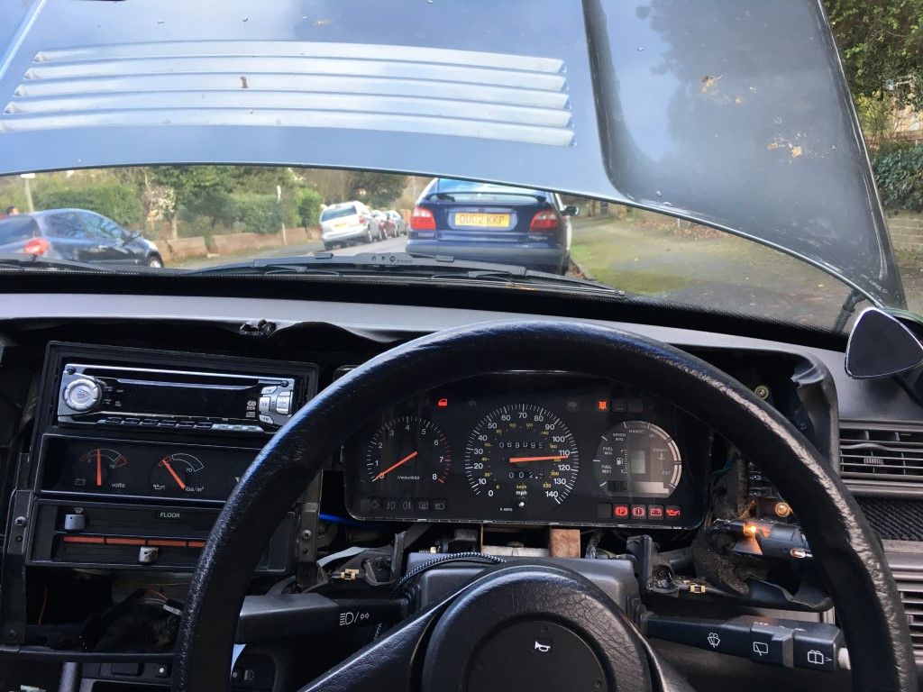
Of course, the real question is does it work. Well, on the bench it does:
video link
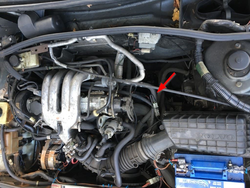
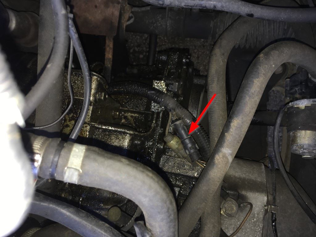
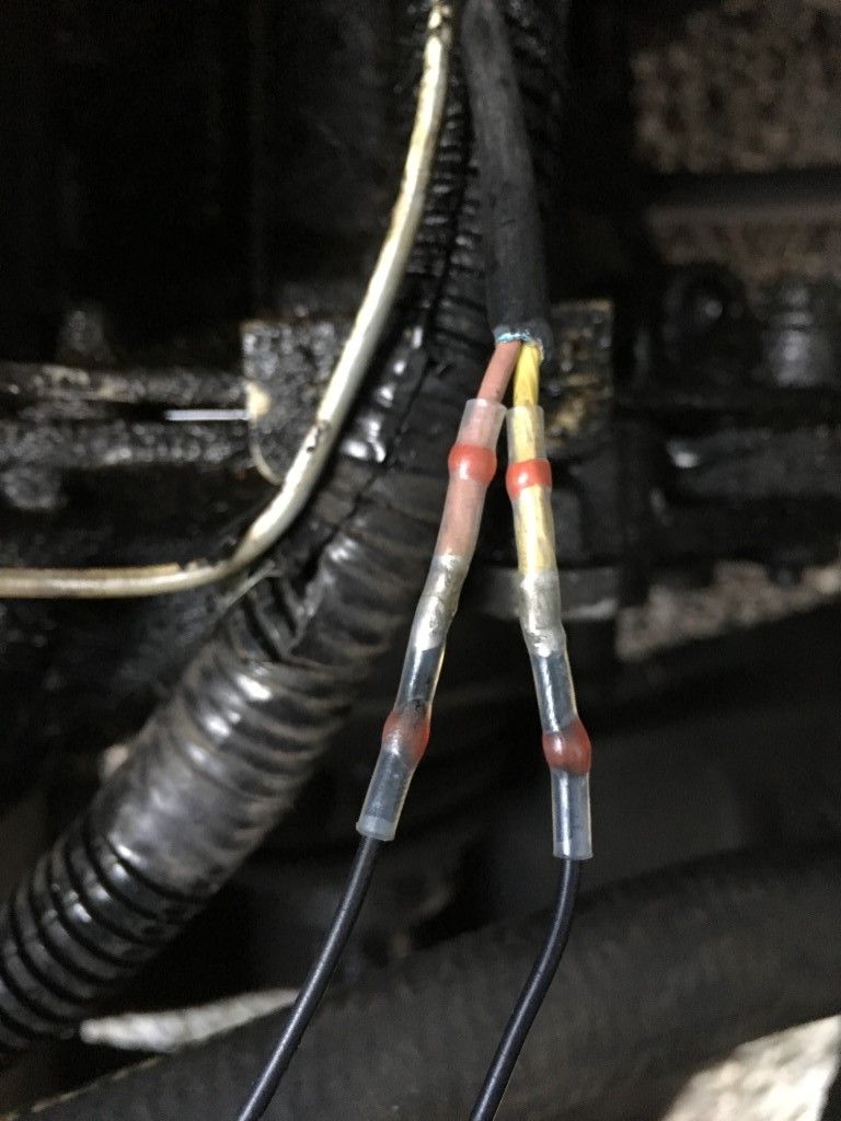
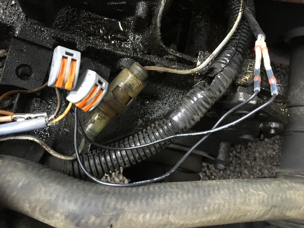
However, in the car it does not. This is the interesting bit (relatively speaking). I found the speed sensor connector in the engine bay, and it looked like this:
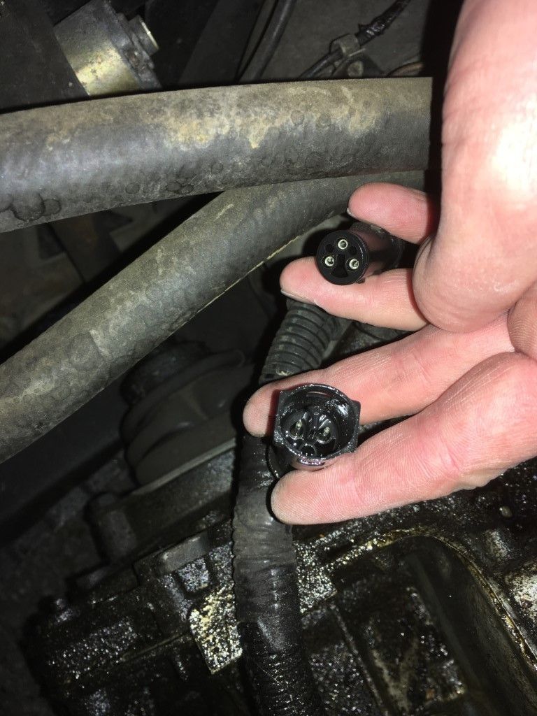
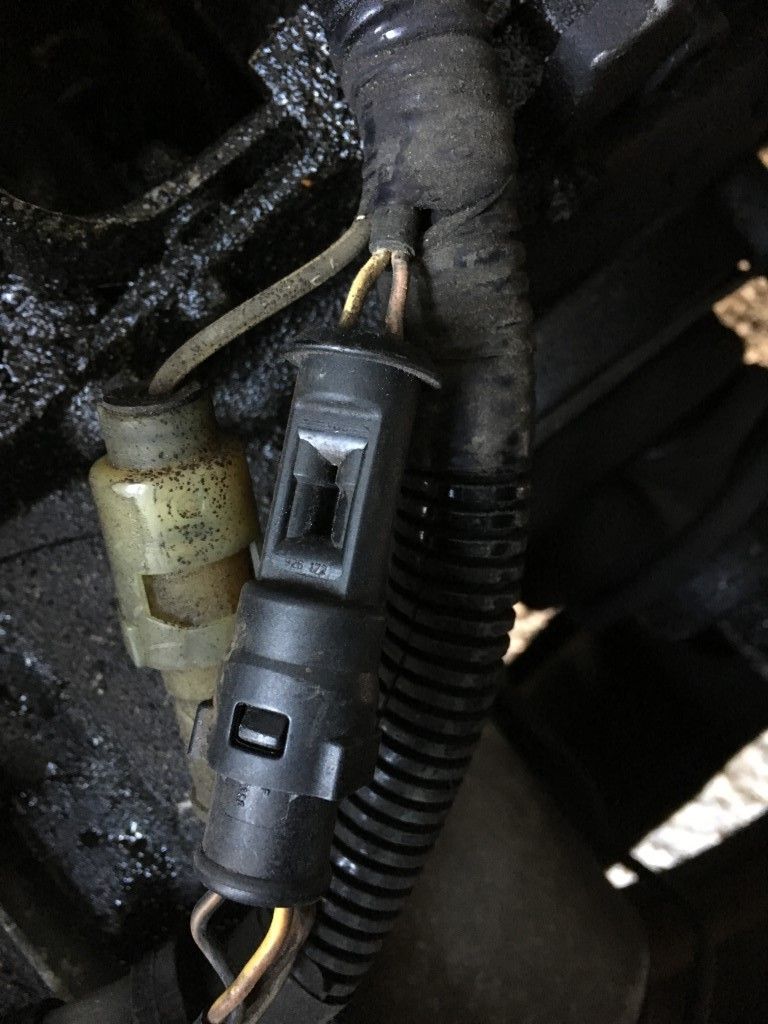
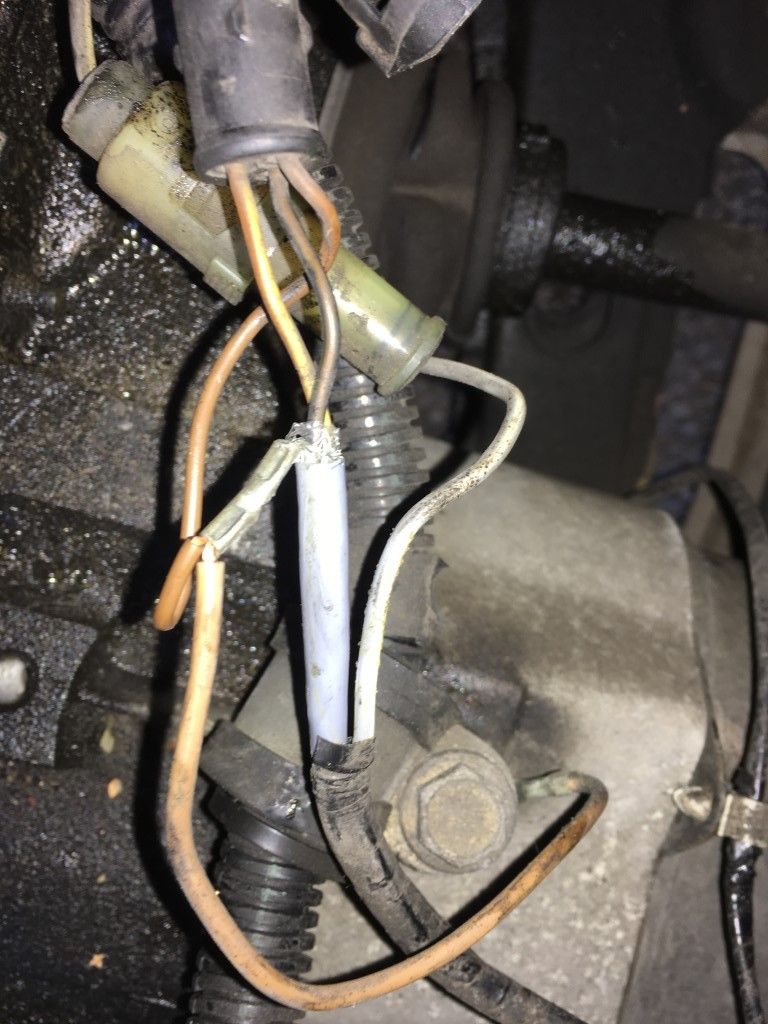
Not entirely what I was expecting, but fine. If I've actually found something else then please somebody tell me and I'll be suitably embarrassed. The lower connector is the one on the sensor side, and gave me about 2 ohms, so the sensor (or whatever is on the other end) is clearly alive. The upper connector is the loom side, and does actually have three wires running to it, although of course only two are in use. It was getting a bit late to start soldering outside, so I liberally applied some contact cleaner and put it back together.
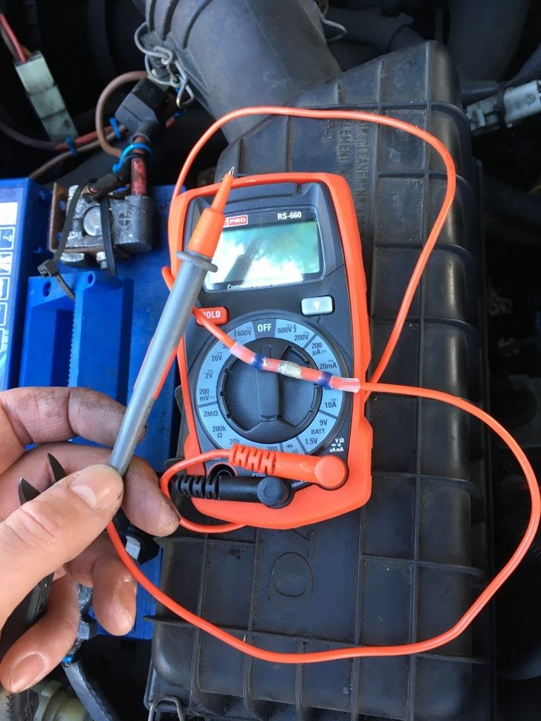
Back inside the car behind the dash, a coax appears and the core goes to one of the multi-connectors, while the shield goes to the other, which again I wasn't expecting. No easily bridging them with a paperclip here. Nonetheless, I got the same 2 ohm reading across the pins, and yet still nothing on the speedo, although everything else on the cluster works perfectly.
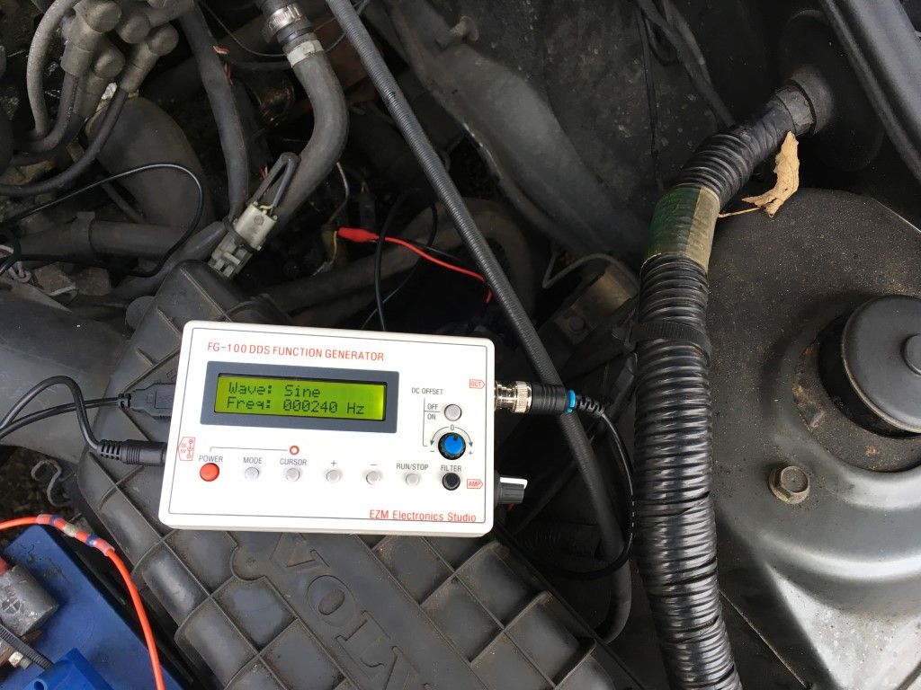
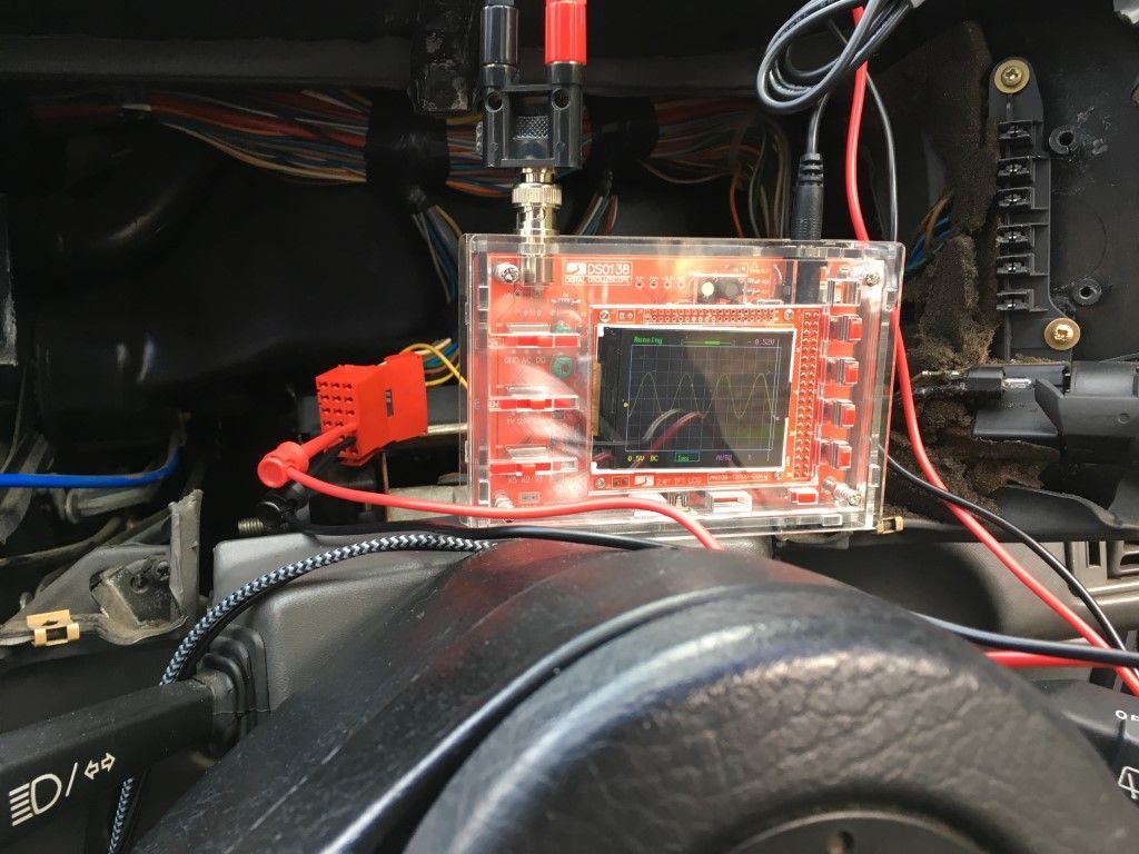
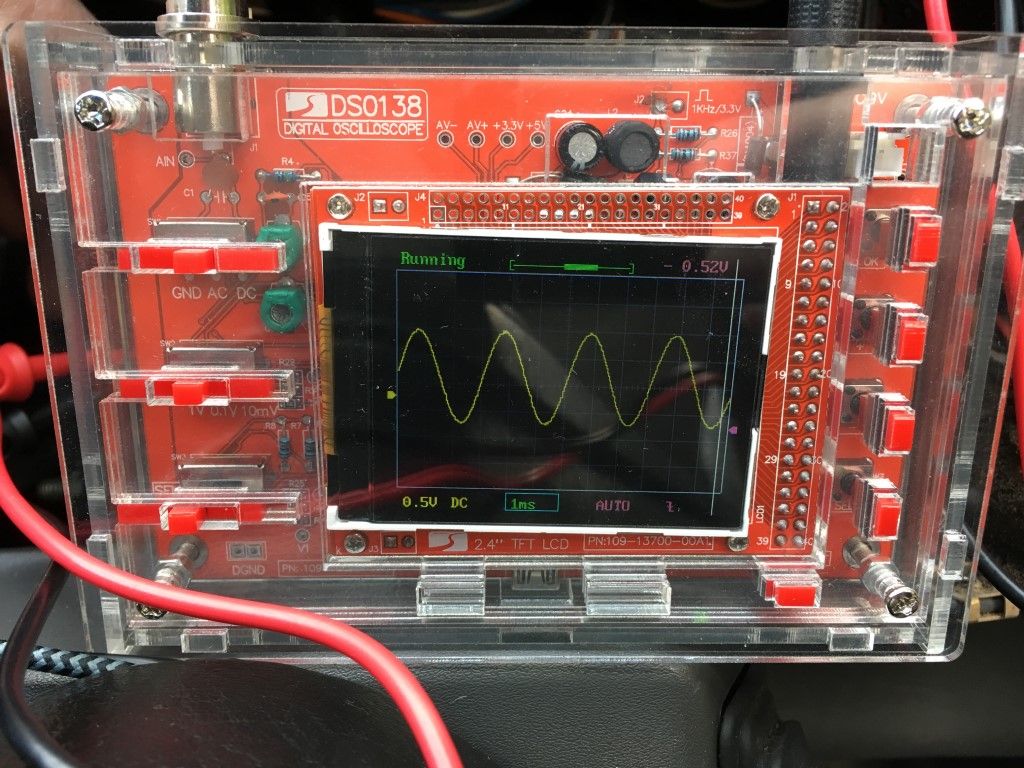
Not really sure what to do next. I'm thinking about hooking up a function generator to the engine bay end and a scope on the dash end to see what happens. I suppose it's possible that the cable is in good enough condition to give a resistance but not enough to maintain the integrity of the signal to the degree required by the cluster. Your thoughts are welcome, and I'll update this as progress is made!
Thanks for reading!
My grey ES was supposed to be restoration project to give me something to fix when I'm not already fixing the green GT, but the other half has been using it to commute in so not a huge amount has happened to it, until she told me last week that the speedo had stopped working. "No problem", I thought naievely, "I'll repair a few connections here and there, give it a clean, and it'll be back up and running in no time. How wrong I was.
Being an '88 car it has the older style pins-through-the-board arrangement to connect to the speedo rather than the nicer ribbon cable and blue connector found on the back of newer clusters, and when I got it out it looked like this:
To my eyes this looks like it was repaired by an agry gorilla. In general I support the return of public flogging for people who solder those pins in an attempt to do a quick fix on the speedo, but this was something else. Not only were the pins soldered solid, they were all bent out of shape and he's managed to melt the plastic connector and warp it, which might go some way to explaining how hard it was to unplug. They're never easy, but this one was noticeably less willing to come out than normal.
I had to apply far more heat and brute force than I would have liked to get the thing apart. Owing to the design (and the damage) it was very hard to remove the solder by conventional means, and when I finally got the board off, the underside looked like this:
Not pleasant. A combination of heat and shearing force ripped the pads straight off the board. I'll take some responsibility for that, but I'll also lay some blame at the door of the aforementioned primate who forced me to take this drastic action in the first place.
I did the usual re-flow job on the big connectors and then paused to consider my next move toward getting the speedo connected again. Was I disheartened? Slightly, but not enough to give up. I exposed some nice clean copper further up the traces and ended up with this:
Note that the top speedo pin actually has a trace running straight through to the other side, so I exposed some extra copper on that along with some on the trace below the pins. Next, I drilled out some holes, starting at 0.6mm and ending at 1.1mm, going very slowly. These are old boards and I didn't want to risk ripping the whole trace off the surface (again):
Thankfully, these are very simple single-layer boards so can be drilled through without risk of destroying something in the middle. In fact, all I'm really doing here is adding to the existing through-hole connections on the other side. A bit of flux and solder later and it almost looks like they were supposed to be there:
Looking at the the other side of the board it becomes easier to see what's going on:
The orange single-core is bridging across that link from the top speedo pin to the trace at the bottom that was broken (and doesn't even look out of place compared to the similar black wire in the top right that's there from the factory), and the red, green, purple and black connectors are playing the role of the now-destroyed headers. The observant reader will notice that I soldered them again, but this time around I know that the underside of the board is in good condition because I've seen it (and fixed it) myself, and I could remove those wires to get into it again in less than 5 seconds, versus the half hour or so it took me to sort out the ruined pins initially.
Of course, the real question is does it work. Well, on the bench it does:
video link
However, in the car it does not. This is the interesting bit (relatively speaking). I found the speed sensor connector in the engine bay, and it looked like this:
Not entirely what I was expecting, but fine. If I've actually found something else then please somebody tell me and I'll be suitably embarrassed. The lower connector is the one on the sensor side, and gave me about 2 ohms, so the sensor (or whatever is on the other end) is clearly alive. The upper connector is the loom side, and does actually have three wires running to it, although of course only two are in use. It was getting a bit late to start soldering outside, so I liberally applied some contact cleaner and put it back together.
Back inside the car behind the dash, a coax appears and the core goes to one of the multi-connectors, while the shield goes to the other, which again I wasn't expecting. No easily bridging them with a paperclip here. Nonetheless, I got the same 2 ohm reading across the pins, and yet still nothing on the speedo, although everything else on the cluster works perfectly.
Not really sure what to do next. I'm thinking about hooking up a function generator to the engine bay end and a scope on the dash end to see what happens. I suppose it's possible that the cable is in good enough condition to give a resistance but not enough to maintain the integrity of the signal to the degree required by the cluster. Your thoughts are welcome, and I'll update this as progress is made!
Thanks for reading!